Designing 3D Printed Assemblies: Practical Clearance Guide
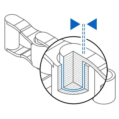
Mating parts require carefully planned clearance offsets to fit together smoothly. Without sufficient clearance, parts will seize or require laborious post-processing; too much clearance results in loose, wobbly assemblies. This design guide breaks down recommended clearance values by assembly type—clearance fits, moving joints, snap fits, and press fits—along with practical verification workflows.
Perfect in CAD, Unusable in Reality
One of the most common frustrations in 3D printing is discovering that components modeled with zero gap in CAD fail to assemble after printing. Real-world manufacturing involves material shrinkage and process tolerances that CAD models do not inherently reflect. Designing intentional clearance into your geometry is the cornerstone of successful functional assemblies.

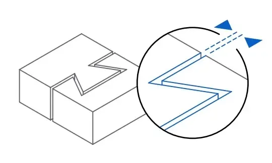
Clearance offset between interlocking parts and snap-fit joints (Source: Formlabs Fuse Series SLS Design Guide).
Common Pitfalls of Incorrect Clearance
Improper clearance choices directly disrupt assembly performance and product quality:
Zero Clearance: Parts cannot fit together, requiring manual sanding, reaming, or complete reprints.
Excessive Clearance: Mating components fit loosely, introducing backlash and mechanical instability.
Unaccounted Shrinkage: Resins and thermoplastics shrink anisotropically, warping bore holes and mating bosses.
Frozen Kinematic Joints: Hinges and sliding mechanisms printed with inadequate spacing will bind or fuse during production.
Scaling Functional Print-in-Place Assemblies
Industrial SLS (Selective Laser Sintering) technology enables print-in-place mechanisms where pre-assembled, movable joints are printed in a single build without secondary assembly. Achieving functional moving parts straight out of the powder cake hinges entirely on precise clearance offsets. Mastering clearance design has become an essential skill in Design for Additive Manufacturing (DfAM).
Clearance: Compensating for Material Realities
Clearance is the intentional distance designed between two mating surfaces. The optimal value depends on several critical factors:
Material Shrinkage: Photopolymer resins contract during curing (SLA), while semicrystalline polyamides contract as they cool from the melt (SLS).
Printer Resolution: Laser spot diameter and beam compensation affect outer contours and internal cavities.
Build Orientation: Holes oriented along the Z-axis often deviate in circularity compared to XY-plane features.
Part Dimensions: Larger parts accumulate thermal strain and dimensional deviations across longer spans.
The golden engineering rule is to use standard reference clearances and validate them with small calibration coupons prior to volume production.
Recommended Clearance Values by Joint Type
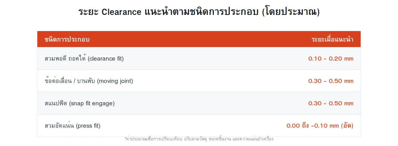
General clearance guidelines for functional 3D printed mechanical fits.
Joint Type | Recommended Clearance (Approximate) |
|---|---|
Clearance Fit (Removable) | 0.10 – 0.20 mm |
Moving Joint / Hinge | 0.30 – 0.50 mm |
Snap Fit | 0.30 – 0.50 mm (Engagement Clearance) |
Press Fit (Interference) | 0.00 to -0.10 mm (Shaft larger than bore) |
These values serve as practical starting points. SLS nylon generally requires slightly larger offsets than SLA resin due to particle sintering and surface texture. Always produce a fit-test coupon for critical functional tolerances.
Real-World Application Examples
Common industrial use cases where precise clearance is vital:
Enclosure Covers: A 0.15 mm radial offset ensures snap-together lids close securely without binding.
Print-in-Place SLS Hinges: A 0.40 mm gap around the pivot pin lets unsintered nylon powder evacuate freely, yielding smooth rotation immediately.
Alignment Dowels: Printing a multi-gauge step block lets teams pinpoint the ideal slip-fit dimension before committing to full assemblies.
“Printing a stepped tolerance gauge upfront allowed us to nail the exact fit immediately, completely eliminating manual post-filing.”
— Engineering feedback from product development teams
Optimize Your Fit with 3DQuickPart
3DQuickPart by AppliCAD helps engineers and makers dial in exact clearances across engineering materials—from high-detail SLA resins on the Formlabs Form 4L to robust PA12 nylon on the Formlabs Fuse 1+. Upload your CAD file to verify clearances and receive an instant online quote.
Get an instant quote and submit your test parts on 3DQuickPart
Consult AppliCAD's additive manufacturing specialists at 095-365-6871 or headquarters at 0 2744 9045, or visit the AppliCAD Innovation Center (AIC) to evaluate physical benchmark prints.
Dial In Your Clearance for Flawless Assembly
Proper clearance is never a static number; it is an engineered balance between material properties, process physics, and functional needs. Applying recommended clearances and validating with test prints ensures seamless assembly from the very first print run.