3D Printing Design Guide: DFAM Best Practices for SLA and SLS
Designing for 3D printing requires more than just creating a watertight 3D CAD model. Design for Additive Manufacturing (DFAM) is the practice of tailoring your component geometry to the physics of layer-by-layer fabrication, ensuring dimensional accuracy, mechanical strength, and minimal manufacturing costs.
At 3DQuickPart, we provide industrial 3D printing services utilizing Formlabs Form 4L (SLA) and Fuse 1+ 30W (SLS) systems. This engineering guide highlights the key design rules and best practices to ensure your components are optimized for production right from the first print.
What is DFAM and Why Does It Matter?
DFAM (Design for Additive Manufacturing) focuses on maximizing part performance while avoiding common additive manufacturing pitfalls. Unlike traditional subtractive CNC machining or injection molding, additive processes build parts layer by layer. This introduces unique thermal, fluid, and gravitational considerations during production.
By applying DFAM principles during the early CAD stage, engineers can prevent layer delamination, minimize warping, reduce material waste, and optimize the surface quality of critical assembly interfaces.
Selecting the Right Process: SLA vs. SLS
Choosing the correct 3D printing technology dictates which design parameters you must follow.
Feature | SLA (Formlabs Form 4L) | SLS (Formlabs Fuse 1+) |
|---|---|---|
Primary Strength | Ultra-high detail resolution and smooth surface finish | High structural integrity, durability, and isotropic strength |
Support Structures | Requires sacrificial support struts | Supportless (unsintered powder bed acts as support) |
Minimum Wall Thickness | Down to 0.2 mm | 0.6 – 0.8 mm recommended |
Internal Assemblies | Requires support removal access | Ideal for complex interlocking & print-in-place mechanisms |
Hollow Geometries | Requires liquid resin drain holes | Requires powder evacuation escape holes |
Best Applications | Visual prototypes, cosmetic enclosures, jigs, master patterns | Functional prototypes, end-use machinery brackets, snap-fits |
8 Essential Design Rules for 3D Printing
1. Maintain Adequate Wall Thickness
Wall thickness directly governs structural stiffness and print reliability. Walls that are too thin risk warping during photopolymer curing or failing to fully fuse during powder bed sintering.
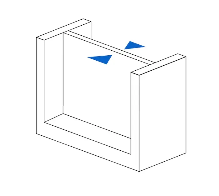
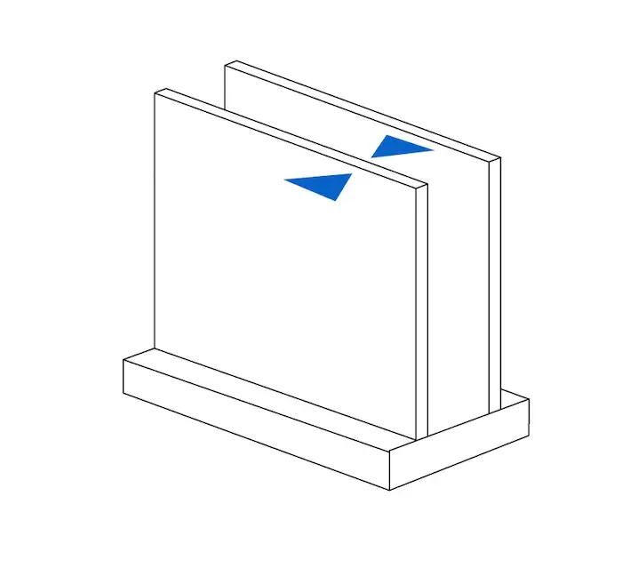
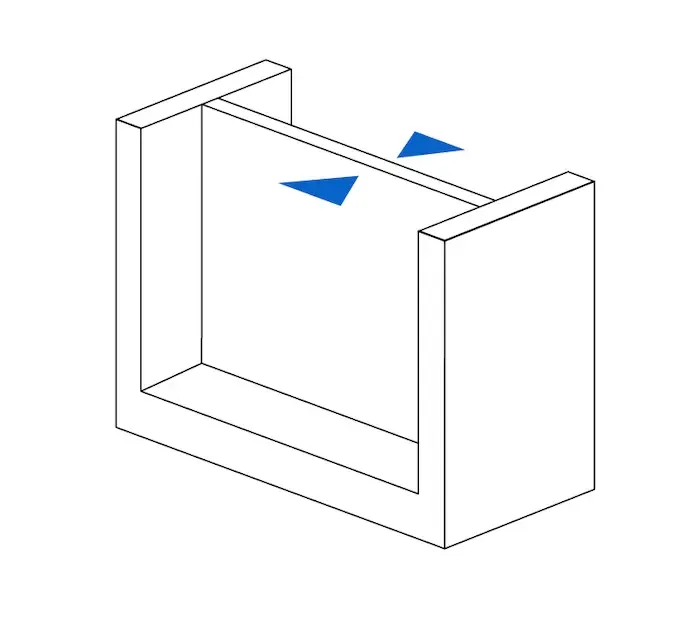
Left: Supported wall (connected on multiple edges). Right: Unsupported wall (cantilevered edge).
For Formlabs Form 4 SLA, the absolute minimum wall thickness is 0.2 mm for both supported and unsupported walls. However, for functional rigidity and handling, a minimum thickness of 0.8 mm to 1.5 mm is strongly advised.
For SLS Nylon 12 on the Fuse series, the minimum printable wall thickness is 0.6 mm for vertical walls and 0.3 mm for horizontal walls. For structural components subject to operational loads, maintain at least 1.0 mm to 2.0 mm to prevent thermal distortion.
2. Control Overhangs and Angles
In SLA printing, downward-facing surfaces with insufficient vertical slope require support structures to prevent sagging.
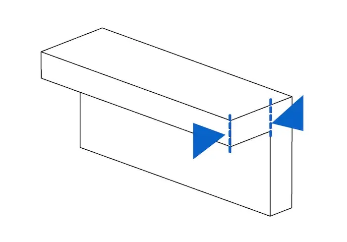
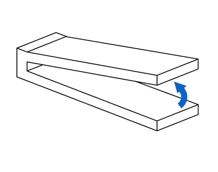
Left: Unsupported overhang span. Right: Overhang inclination angle measured from the horizontal plane.
On the Form 4, unsupported overhangs should not exceed 5.0 mm. Features angled below 10° relative to the build plate risk surface defects and layer dropping without dedicated supports. Mitigate this by applying 45° chamfers or generous fillets to transition unsupported edges back into the main body.
In SLS printing, overhang limitations are virtually eliminated because the self-supporting powder bed holds each layer in place. However, long horizontal spans may experience thermal warpage if not oriented correctly.
3. Size Holes and Internal Channels Accurately
Undersized holes frequently fail due to liquid meniscus bridging in SLA or powder packing in SLS.
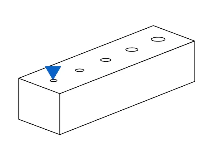
For SLA Form 4 prints, the minimum recommended through-hole diameter is 0.5 mm across all axes to prevent liquid resin from permanently sealing the aperture.
For SLS Fuse 1+ parts, keep internal hole diameters at 1.0 mm or larger across the X, Y, and Z axes to facilitate powder blowout.
When designing clearance holes for fasteners (bolts and dowel pins), always incorporate machining clearance rather than nominal fastener diameters. For instance, design a 5.2 mm to 5.4 mm hole for an M5 bolt to account for resin curing tolerances.
4. Provide Sufficient Assembly Clearances
Mating parts, interlocking hinges, and gears must maintain adequate clearance to prevent premature fusion during the printing process.
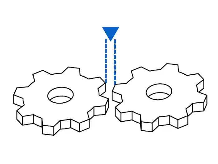
For Formlabs SLA components, provide an assembly gap of at least 0.4 mm between moving or mating faces to ensure smooth articulation.
For SLS print-in-place mechanisms, a gap of 0.3 mm is required for contact areas under 20 mm², while 0.6 mm is recommended for larger mating interfaces to allow loose powder removal.
5. Incorporate Drain Holes and Powder Escape Channels
Hollowing parts reduces material volume, thermal mass, and print duration. However, enclosed cavities create suction cups or trap uncured material.
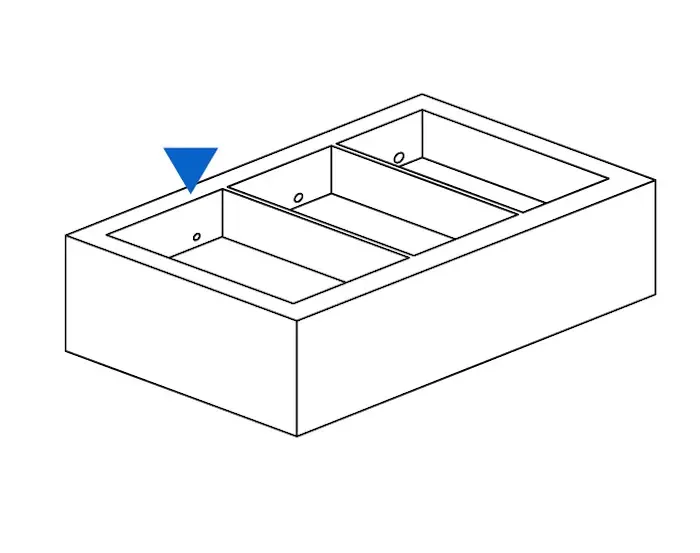
In SLA printing, enclosed volumes generate hydrostatic pressure (cupping effect) that can crack thin walls. Always integrate at least two drain holes with a minimum diameter of 0.75 mm (preferably 2.0 – 3.0 mm) placed at opposite ends of the cavity to allow resin drainage and air venting.
For SLS prints, unsintered powder will remain trapped inside hollow bodies unless evacuated. Design at least two powder relief escape holes of at least 3.5 mm in diameter to facilitate compressed air cleaning.
6. Embossed and Engraved Feature Resolution
Micro-details, lettering, and serial numbers must comply with optical and thermal beam spot sizes.
Detail Feature | SLA (Form 4) | SLS (Fuse 1+) |
|---|---|---|
Embossed Height / Depth | ≥ 0.10 mm (100 µm) | ≥ 0.15 mm (width ≥ 0.35 mm) |
Engraved Depth / Width | ≥ 0.15 mm (150 µm) | ≥ 0.10 mm (width ≥ 0.30 mm) |
Recommended Text Height | ≥ 1.5 mm font height | ≥ 3.0 mm sans-serif font |
7. Design for Post-Processing Access
A successful design accounts for washing, depowdering, and finishing steps. For SLA, orient critical cosmetic faces away from support touchpoints to minimize manual sanding. For SLS, ensure intricate internal channels have line-of-sight access for bead blasting and vacuum media.
8. Optimize Part Orientation
Print orientation dictates anisotropic tensile strength along the Z-axis, visual layer step visibility, and overall build height. Tilting flat planar surfaces at an angle (typically 15° to 45°) reduces cross-sectional peel forces in SLA and minimizes stair-stepping on gently curved contours.
DFAM Pre-Flight Production Checklist
Geometry Integrity: Is the mesh a non-manifold, watertight solid with zero open surfaces?
Wall Thickness: Have all structural walls been verified above minimum safety thresholds?
Drainage / Powder Ports: Are all hollow cavities vented with at least two opposing escape holes?
Clearances & Tolerances: Have moving joints and fastener holes been compensated for process tolerances?
Orientation & Supports: Are critical cosmetic or mating faces positioned away from support structures?
Get an Instant DFAM Evaluation and Quote
You do not have to finalize every tolerance alone. Upload your STL or STEP CAD file to 3DQuickPart Instant Quotation to inspect your geometry, select between SLA resin and SLS nylon, and receive production-ready technical verification from our engineering team.