5 3D Printing File Preparation Mistakes and How to Avoid Them
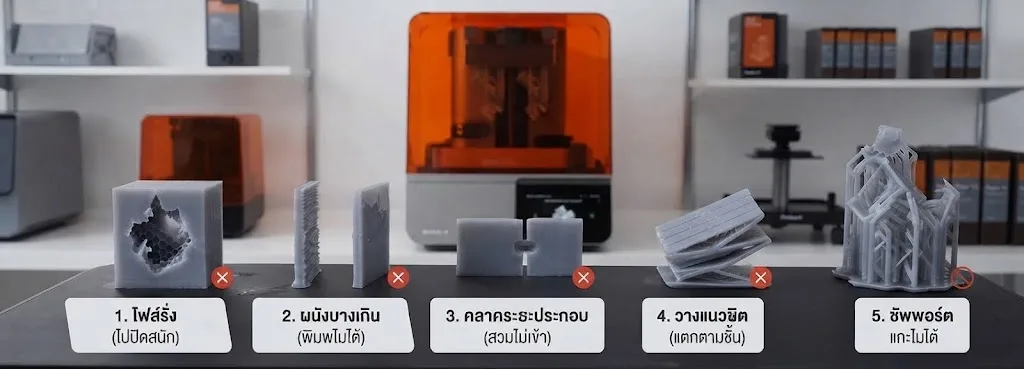
When a 3D print fails, it is natural to question the machine setup, slicing parameters, or resin and powder batches. In practice, however, the majority of print defects are locked in before the start button is ever pressed. Errors introduced during CAD modeling and file export can ruin a build regardless of printer quality. Fortunately, almost all of these issues are preventable with a structured pre-flight check.

Physical examples of failed parts caused by five recurring file preparation oversights.
The Hidden Cost of Failed 3D Prints
Scrapping a failed part wastes far more than raw photopolymer resin or nylon powder:
Lost production time — Industrial prints can run for 10 to 30 hours. A single failure restarts the clock, delaying project deadlines and downstream testing.
Machine and energy overhead — Unproductive machine cycles, post-processing cleanups, and recalibrations inflate operational overhead without generating value.
Engineering confidence — When functional prototypes, jigs, or end-use batches fail repeatedly, production schedules slip and stakeholder trust erodes.
Industrial 3D Printing Demands a First-Time-Right Approach
As additive manufacturing transitions from visual modeling to functional jigs, fixtures, and end-use mechanical components, the “first-time-right” principle becomes critical. Implementing a strict pre-production file checklist eliminates scrap, guarantees predictable turnaround times, and stabilizes unit costs—mirroring the rigorous design validation applied to conventional injection mold tooling.
5 Common File Preparation Mistakes and How to Fix Them
1. Non-Manifold Geometry (Leaky Meshes)
3D models with missing faces, inverted normals, self-intersecting shells, or unstitched edges confuse slicing engines. The software struggles to determine what is solid volume and what is void, leading to missing layers or distorted geometry. Always verify that your STL or 3MF file is a watertight solid manifold, and run an automated mesh repair routine before exporting.
2. Insufficient Wall Thickness
Features thinner than the minimum process threshold will fail to cure or fuse properly, resulting in gaps, warpage, or brittle fractures during support removal. Fine details such as embossed identification labels, snap tabs, and thin cooling fins are especially prone to failure. Review technology-specific design guidelines for SLA or SLS to ensure every wall meets the recommended minimum thickness.
3. Ignoring Thermal Shrinkage and Assembly Clearance
Polymer materials contract as they cool down or cure. When designing mating assemblies, shafts, or enclosures, failing to allocate proper mechanical clearance ensures that mating components will either seize or crack upon assembly. Conversely, excessive clearance causes unwanted play. Specify deliberate design tolerances tailored to your selected technology and resin or nylon grade.
4. Suboptimal Part Orientation
Because additive manufacturing builds objects layer by layer, mechanical properties are anisotropic. When tensile or bending stresses act perpendicular to the build layers (Z-axis), parts can split along layer boundaries. In addition, orientation dictates where support pillars contact the part. Orient your part so primary mechanical loads distribute across the build plane, and angle cosmetic surfaces away from support contact points.
5. Neglecting Support Structures and Drainage
Severe overhangs and steep geometries require auxiliary support structures. Without careful planning, supports may generate inside internal pockets where post-processing tools cannot reach, or leave heavy witness marks on mating faces. For SLA resin printing, enclosed hollow cavities also require properly placed vent and drain holes to prevent vacuum-suction forces (cupping) and trapped liquid resin.
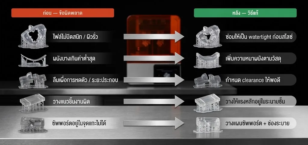
Before and after comparison highlighting the five file preparation mistakes and their technical solutions.
Pre-Flight Check: Comparing the Outcomes
Evaluation Metric | Unchecked File Submission | 5-Point Pre-Flight Check |
|---|---|---|
Failure Rate | High; issues discovered only after post-processing | Low; parts succeed on the first run |
Turnaround Time | Unpredictable due to mandatory reprints | Predictable delivery schedules |
Cost per Part | Inflated by scrap resin, powder, and labor | Controlled and budgeted accurately |
Dimensional Quality | Inconsistent fit and mechanical performance | Consistent, production-grade precision |
Real-World Examples: Rescued Before Slicing
Practical engineering scenarios where pre-flight file checks prevented costly failures:
Embossed Part Numbering on Housings — Pre-print mesh verification flagged text stroke widths below 0.6 mm, allowing designers to thicken the font for crisp legibility in SLA.
Snap-Fit Enclosures — Adjusting mechanical clearances by 0.3 mm to account for nylon PA12 powder fusion tolerances allowed interlocking parts to mate smoothly on the first attempt.
Third-Party CAD Meshes — Running an automated geometry repair on an exported STL closed non-manifold open surfaces, preventing the slicer from dropping interior features.
“Adopting a pre-flight file checklist cut our scrap rate dramatically. We no longer lose valuable days waiting for duplicate print runs.”
Upload Your File for Expert Pre-Print Review
At 3DQuickPart by AppliCAD, every model is reviewed by additive manufacturing specialists before production begins. We inspect mesh integrity, wall thicknesses, mating clearances, build orientation, and support layout on Formlabs Form 4L (SLA) and Fuse 1+ (SLS) systems. If any design risk is identified, our team provides practical feedback to ensure your parts print right the first time.
Speak with AppliCAD technical experts and submit your STL files for instant quoting at 3DQuickPart.
Direct: 095-365-6871 | Head Office: 0 2744 9045 | AppliCAD Innovation Center (AIC)
Verify Before You Print
Dependable 3D printing requires reliable digital engineering, not just a capable printer. By inspecting these five critical checkpoints—watertight geometry, adequate wall thickness, proper clearance, optimal orientation, and accessible support placement—you eliminate the root causes of print failure, save valuable machine hours, and secure predictable project outcomes.