Minimum Wall Thickness Guide: SLA vs SLS 3D Printing
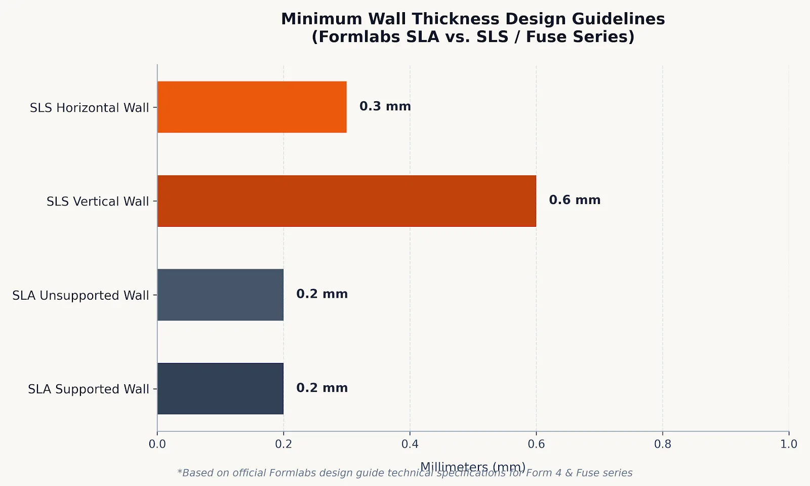
Wall thickness is one of the most critical engineering parameters governing the success, strength, and unit cost of 3D-printed parts. Walls that are modeled too thin frequently fail during printing, tear under mechanical handling, or warp during post-processing. Conversely, excessively thick solid walls waste material, extend production cycles, and create thermal stresses that induce sink marks and deformation. Understanding the minimum and recommended wall thickness thresholds for Stereolithography (SLA) and Selective Laser Sintering (SLS) is essential for producing reliable, functional parts.
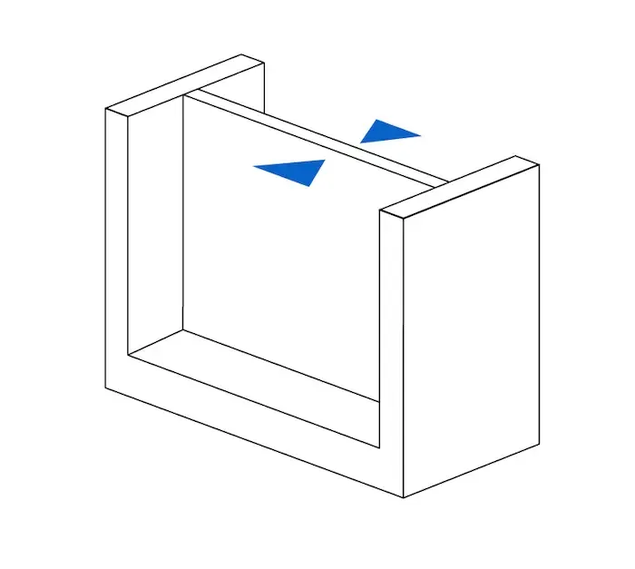
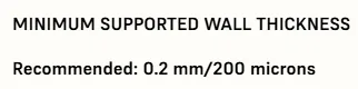
Supported walls connected to structural features on multiple sides retain geometry far better than free-standing unsupported walls, allowing significantly thinner cross-sections.
Common Failures Caused by Sub-Optimal Wall Thickness
Designing features below the manufacturing limits of a 3D printing process leads to several predictable issues:
Delamination and Non-Fusion: If a wall is narrower than the laser beam spot diameter or powder particle resolution, the slicing software cannot generate toolpaths, leading to missing geometries or perforated sections.
Brittleness and Handling Damage: Extremely thin sections cannot resist demolding stresses, such as peeling forces in SLA resin vats or pressurized abrasive media during SLS bead blasting.
Thermal Warping and Internal Stresses: Broad, thin walls undergo uneven shrinkage. In SLA, residual stresses from UV post-curing cause thin plates to curl. In SLS, temperature gradients across the powder cake induce warping.
Loss of Fine Features and Text: Undersized embossing, debossing, and delicate snap-fit cantilevers may round off, break, or disappear entirely.
Why SLA and SLS Have Different Wall Thickness Constraints
The physics of material consolidation dictate the geometric limits of each technology:
SLA (Stereolithography): Photopolymer liquid resin is cured layer-by-layer using a focused UV laser or light engine. Because the focal point is exceptionally sharp, SLA can resolve supported vertical walls down to 0.2–0.4 mm. However, uncured resin parts are in a soft "green state" before post-curing; unsupported thin walls may bend under peeling forces or sag under their own weight.
SLS (Selective Laser Sintering): A CO2 or fiber laser sinters fine thermoplastic powder, such as Nylon PA12. The minimum wall thickness is limited by powder grain size and heat conduction into adjacent un-sintered powder (heat-affected zone), yielding practical minimum walls of 0.6–0.8 mm. Because the surrounding unsintered powder bed acts as a continuous self-support, SLS requires no dedicated support structures, offering superior freedom for complex, freeform geometries.

Design guidelines for minimum wall thickness across Formlabs SLA (Form 4 series) and SLS (Fuse series) platforms.
Comparison: SLA Resin vs SLS Nylon PA12 Wall Specifications
Use the following technical parameters when preparing CAD models for SLA and SLS manufacturing:
Design Feature | SLA Photopolymer Resin (Formlabs Form 4L) | SLS Nylon PA12 (Formlabs Fuse 1+) |
|---|---|---|
Minimum Supported Wall | 0.2 – 0.4 mm | 0.6 mm (vertical) / 0.3 mm (horizontal) |
Minimum Unsupported (Free-standing) Wall | 0.8 – 1.0 mm | 0.8 – 1.0 mm |
Recommended Functional Wall Thickness | 1.5 – 2.0 mm | 1.2 – 2.0 mm (1.5 mm optimal for tensile strength) |
Maximum Practical Wall Thickness | 4.0 – 5.0 mm (prevent cure shrinkage) | 6.0 – 8.0 mm (prevent thermal sinks and warping) |
Embossed / Engraved Details | Embossed ≥ 0.1 mm / Engraved ≥ 0.15 mm | Feature width ≥ 0.5 – 1.0 mm (text height ≥ 2.0 mm) |
Hollow Drain / Escape Holes | Minimum 1 hole, diameter ≥ 3.5 mm | Minimum 2 holes, diameter ≥ 5.0 mm |
Clearance for Moving / Interlocking Parts | ≥ 0.3 mm | 0.3 – 0.5 mm |
Lightweighting Strategies Without Compromising Structural Integrity
Effective Design for Additive Manufacturing (DfAM) achieves lightweight structural performance without pushing walls past their failure limits:
Incorporate Structural Ribs: Instead of thickening an entire panel to withstand bending, maintain a baseline wall of 1.2–1.5 mm and stiffen it with structural ribs. Rib thickness should be approximately 50–60% of the nominal wall to avoid localized sink marks.
Hollowing with Adequate Escape Ports: Bulky solid cross-sections should always be hollowed. SLA hollow models require drain holes of at least 3.5 mm to relieve vacuum suction during platform peeling. SLS hollow components require at least two 5.0 mm holes to allow un-sintered powder evacuation during post-processing.
Fillet Transitions: Sharp interior corners concentrate stress and cause crack propagation. Applying fillets with a radius of 0.5–1.0 mm significantly improves impact resistance and resin/powder flow.
Validate Your 3D CAD Files with 3DQuickPart
Before launching batch production or prototyping high-precision components, verifying wall thickness ensures first-time printing success. 3DQuickPart by AppliCAD provides automated file verification, process selection advice, and industrial 3D printing services using Formlabs Form 4L SLA and Fuse 1+ SLS systems.
Upload your 3D CAD model for instant thickness validation and quoting at 3DQuickPart Instant Quote, or consult our engineering team directly at 095-365-6871 (Headquarters: 0 2744 9045) or visit the AppliCAD Innovation Center (AIC).