Why Part Orientation Dictates 3D Printing Strength and Quality
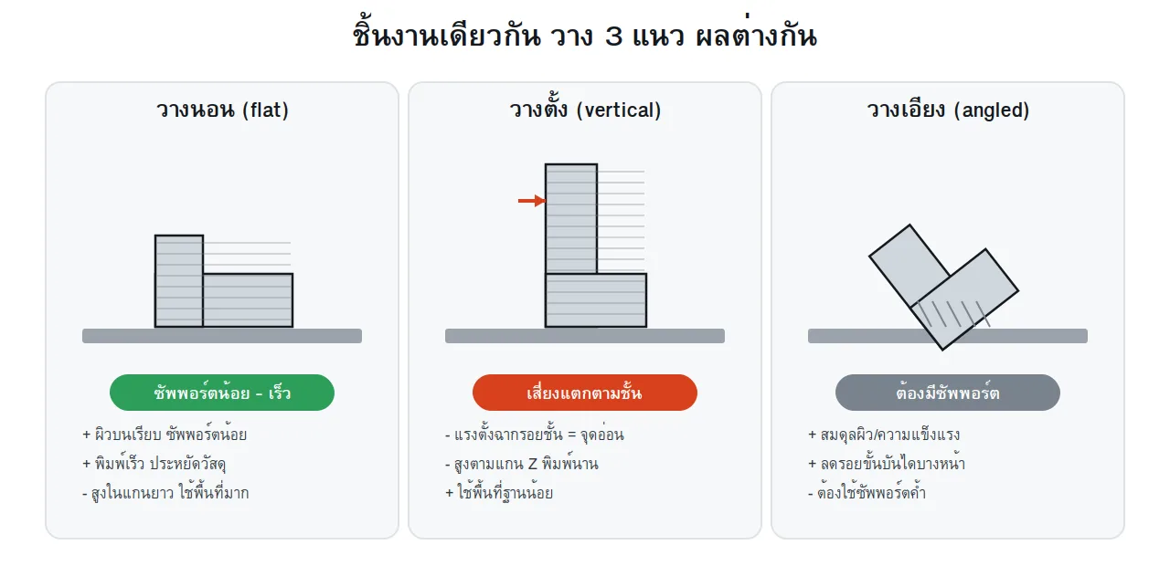
It is common to assume that 3D printing simply requires loading a CAD file and hitting start. However, in industrial additive manufacturing, build orientation is one of the most critical engineering decisions. The same model printed flat, vertically, or angled can produce vastly different mechanical strengths, surface finishes, and cycle times.
Why the Z-Axis Determines Weak Points and Resolution
Additive manufacturing processes build parts layer by layer along the vertical Z-axis. This fundamental mechanism introduces two defining physical behaviors:
Anisotropy (Directional Mechanical Strength): The molecular or fused bond within a single layer (XY plane) is consistently stronger than the interlayer bond along the build direction (Z-axis). Tensile or bending stresses applied perpendicular to the layer boundaries can easily delaminate the part.
Z-Axis Resolution and Stair-Stepping: While XY resolution is governed by laser spot size or nozzle diameter, Z-axis fidelity is constrained by layer thickness. Gradual slopes and curved faces naturally exhibit visible stair-stepping artifacts if oriented incorrectly.
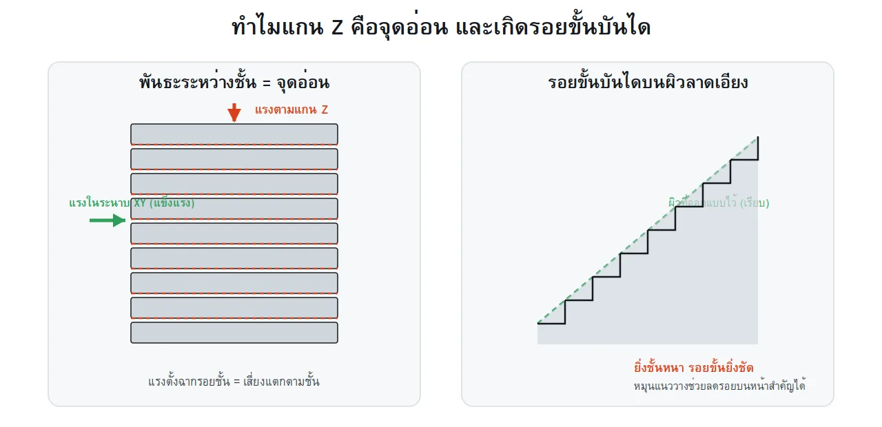
Diagram illustrating Z-axis interlayer weakness under load and stair-stepping across sloped geometries
Same Geometry, Different Orientation: Drastic Differences
Rotating a part inside the build volume influences four primary operational metrics: mechanical load capability, critical surface finish, required support structures, and overall build duration.

Trade-off comparison between flat, vertical, and angled part orientations
Evaluating standard orientation strategies reveals clear engineering trade-offs:
Orientation Strategy | Key Advantages | Primary Constraints |
|---|---|---|
Flat Orientation | Fastest build time due to low Z-height; minimal supports required; smooth top surfaces. | Occupies significant build platform area; broad cross-sections increase peeling stress in resin. |
Vertical Orientation | Small footprint allows more parts per batch; uniform radial surface texture. | Longest build time due to layer count; weakest against lateral bending stresses. |
Angled Orientation | Distributes peel forces, reduces visible stair-stepping, and balances directional strength. | Requires support structures on downward-facing features. |
Process-Specific Orientation Guidelines
Each additive manufacturing technology relies on different physical mechanics. Applying proper orientation rules ensures optimal results for each process.
1. SLA Technology (Stereolithography - High-Precision Resin)
SLA uses light polymerization to cure photosensitive liquid resin layer by layer. While isotropic bonding is higher than in FDM, the separation forces during vat peeling present serious mechanical challenges.
Angled Tilting (10–20 Degrees): Orienting parts at a slight angle prevents large, flat cross-sections parallel to the vat, significantly reducing peel forces.
Preventing Suction Cups: Hollow geometry oriented downwards creates a vacuum against the vat film, risking puncture, part detachment, or delamination.
Minima and Overhang Management: Proper orientation ensures that new features originate smoothly above support touchpoints without unsupported overhangs.
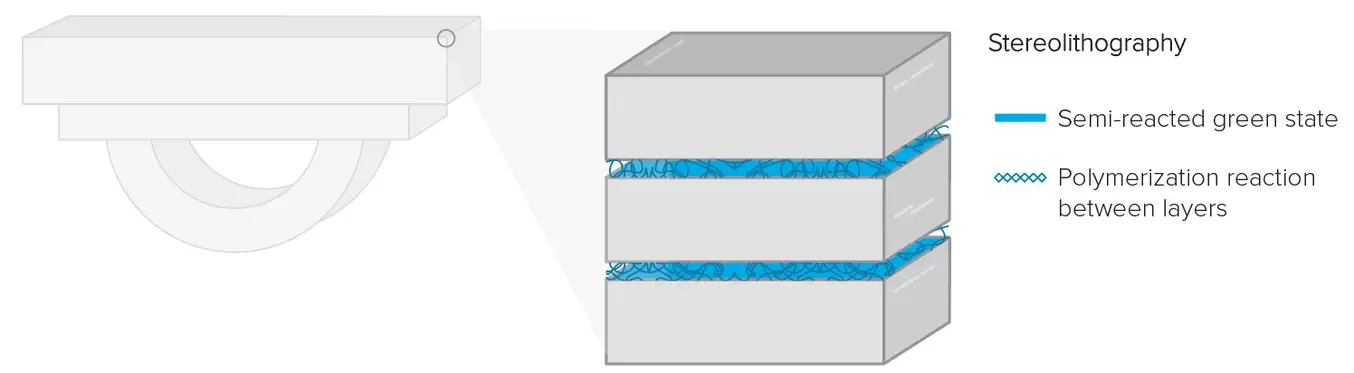
Photopolymer cross-linking across layers in stereolithography
2. SLS Technology (Selective Laser Sintering - Industrial Nylon)
SLS sinters polymer powders like Nylon PA12 with an industrial laser. The surrounding unsintered powder acts as self-supporting media, eliminating the need for rigid support structures.
3D Nesting Efficiency: Parts can be rotated, angled, and packed densely throughout the build chamber, maximizing throughput per print cycle.
Mitigating Thermal Warpage: Large, slender components oriented horizontally can warp due to non-uniform thermal dissipation. Angling them distributes heat buildup more evenly.
Critical Surface Orientation: Upward-facing and downward-facing surfaces exhibit slight texture variations. Orienting non-critical surfaces towards the powder bed simplifies post-print bead blasting.
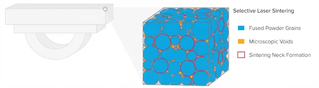
Laser-fused powder microstructures and necking formation in SLS nylon
3. FDM Technology (Fused Deposition Modeling - Extruded Filament)
FDM relies on mechanical bonding between extruded thermoplastic beads, making anisotropic effects especially prominent.
Load Alignment with the XY Plane: Inter-layer bonding is vulnerable to tensile stress. Always orient the part so expected service loads run parallel to the deposited filament tracks.
Overhang Angle Reduction: Keep overhang angles below 45 degrees to avoid excessive support material, minimizing post-processing marks and post-print cleanup.
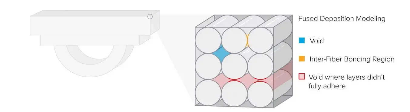
Microscopic voids and inter-fiber bonding regions characteristic of FDM printing
Technology Comparison Summary
Technology | Key Orientation Considerations | Benefits of Correct Setup |
|---|---|---|
SLA (Resin) | Minimize peel forces, eliminate suction cups, tilt 10–20° | Prevents vat detachment, maintains crisp details and smooth finish |
SLS (Nylon) | 3D nesting optimization, avoid thermal warpage on flat faces | Near-isotropic mechanical properties, high batch efficiency |
FDM (Filament) | Align functional loads along XY plane, limit steep overhangs | Eliminates premature layer separation, reduces support waste |
Practical Engineering Checklist for Build Preparation
Before launching a production run, verify your design against these functional orientation guidelines:
Functional Snap-Fits and Cantilever Clips: Orient the flexure arm parallel to the build platform so bending stress does not split the layers apart.
Shafts, Pins, and Fastener Bores: Position circular shafts vertically for tight radial concentricity, or horizontally if the component experiences heavy shear loads.
Aesthetic Markings and Fine Text: Face raised or debossed text upward or away from support connection points to preserve clean definition.
Orientation is not merely software setup—it is a cornerstone of Design for Additive Manufacturing (DfAM). For high-precision functional parts in resin (SLA) or nylon (SLS), upload your CAD file directly for automated design checks and instant pricing at 3DQuickPart Instant Quote.